
Electrical Enclosure Cable Entry and Panel Cutouts: A Technical Guide
An electrical enclosure keeps its ingress protection only when the cable entries, the panel cutouts and the door seal are specified on the same drawing as the housing. The box is one component of the assembly. Every gland hole, meter opening and door joint is an interface where protection has to be re-established after the sheet is cut, and each one fails in a different way.
Yinlu (Dalian Yinlu Electrical Control Equipment Manufacturer) is a Dalian, China manufacturer of sheet metal fabrication, electrical enclosures and electrical control cabinets that also accepts OEM and ODM orders. Its recorded customization scope covers material, colour, logo, size, IP rating, surface treatment, and cutouts and mounting — the same variables this guide asks you to write down before production starts.
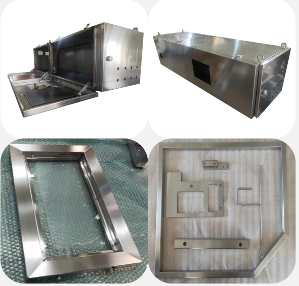
Why the entries and cutouts decide the protection level
A CE verification or a type test describes a defined configuration: one cabinet, one gasket, one door hardware set. Remove a knockout, punch a pushbutton hole or cut a meter window and the assembly becomes a different configuration. At that point the water and dust path is set by the component fitted into the opening and by the way the opening was made, not by the housing that was tested.
Three patterns account for most of the problems on site:
- Knockout and gland mismatch. A pre-scored knockout is a fixed size. If the specified gland has a smaller thread, the sealing washer has no flat land to sit on, and no amount of tightening will close the gap.
- Cutouts drawn without a datum. Openings dimensioned from the door centre or from an approximate edge drift between units, and a meter bezel needs a defined flat land to seal against.
- Hardware on the sealing line. A lock, hinge or door-mounted instrument that penetrates the gasket path opens a leak unless the detail provides a local seal or routes the gasket around the component.
The commercial question follows from this: who cuts the openings? If the factory cuts them, they can be inspected against the drawing and included in the sealing check. If the installer cuts them on site, the declared protection no longer describes the installed assembly, and any leak becomes a site dispute. Decide the split before the purchase order.
What the standards fix, and what they leave to your drawing
Two documents do most of the work. IEC 60529 describes a system for classifying the degrees of protection provided by enclosures of electrical equipment, and the rating uses two digits: the first covers protection against solids and dust, the second covers protection against water. At the level usually written for outdoor cabinets, IP66 means the enclosure is dust-tight and protected against powerful water jets.
IP and NEMA are not interchangeable. NEMA enclosure types address additional hazards including corrosion, rust, icing, oil and coolants, which is why there is no complete equivalency between the two systems. The voltage scope also comes from different documents: ANSI/NEMA 250-2020 covers enclosures for equipment rated not more than 1,000 V, while ANSI/IEC 60529-2020 applies to equipment with a rated voltage not exceeding 72.5 kV. For a low-voltage panel enclosure in North America the NEMA scope is the binding one; for an IEC-based project specification the IP code is the reference.
Market figures explain why the detail matters commercially without changing the engineering. Fortune Business Insights estimates that metallic enclosures, including stainless steel and aluminium, will hold a 52.81% share of the electrical enclosure market in 2026, and that Asia Pacific accounted for 36% of the global market in 2025. Metal housings dominate, and metal housings are exactly the products where entry and cutout work happens after the box is formed.
What the standards never tell you is which face to enter, what size to cut, or where the gasket joint should sit. Those are drawing decisions, and they are where specifications usually fail.
The three interfaces to specify

Cable entry: bottom and pedestal knockouts
Bottom entry is the default for floor-standing cabinets because gravity then works with the seal instead of against it. The entry detail has five parts, and all five belong in the schedule.
- Face and height. A cable entering at the very bottom of a floor-standing cabinet has almost no room for a drip loop before it meets the gland plate. State the height of the entry above the plinth or floor line.
- Knockout or cut opening. A knockout is useful where the installer may need an extra entry later, but the removed edge is less controlled than a punched opening and the size is fixed by the tool. Where the gland is already known at order stage, an opening cut to the gland thread gives a cleaner seat.
- Gland selection. A waterproof cable gland seals on two surfaces — the cable jacket, through an insert sized to the cable diameter range, and the enclosure wall, through a washer or O-ring against a flat land. A gland chosen only by thread size can still be wrong for the cable.
- Thread engagement. The gland body and locknut need enough material to compress the wall seal and hold torque. On thin sheet, or on a large gland, a local reinforcing pad or a separate gland plate is the usual answer.
- Spare capacity. State how many spare entries are needed and whether they ship with blind plugs or stay closed. A spare entry at build stage costs far less than a field punch.
Pedestal entry follows the same logic: the cable rises inside the plinth and passes through the cabinet floor, so the seal sits at the floor plate and the plinth itself must drain or be sealed. A cabinet standing on a raised floor or a concrete plinth has a floor gland, not a wall gland.
Panel cutouts: instruments, buttons and meters
Cutouts are dimensioned work, and the drawing should behave like a machining drawing even though the part is sheet metal.
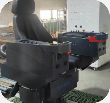
- Two datums, not one. Fix an X datum and a Y datum — a corner or a trimmed edge — and dimension every opening from them. Chain dimensions from an approximate edge are what make an opening drift between units.
- Edge distance. An opening close to a bend or to the door edge leaves little material to carry the device, and the land distorts when the sheet is formed or coated. Set a minimum land around each opening and move the device layout rather than shrinking the land.
- Corner radius. Rectangular meter and HMI windows should carry a corner radius; a sharp internal corner concentrates stress and is difficult to coat cleanly.
- Device family. Pushbuttons, selector switches and signal lamps take round openings; meters and displays take rectangular openings sized to the bezel rather than to the display glass; an HMI window needs a land wide enough for the window gasket.
- Door-mounted or body-mounted. A device on the door moves with the door, so its wiring has to cross the hinge line through a loop or a terminal block, and the opening interrupts the door gasket line unless the device is sealed to the door face.
- Tolerance and rework. State the tolerance band and who owns rework if a cutout falls outside it. This single sentence prevents most cutout arguments.
Door sealing: EPDM gasket, single or double door, flat or handle lock
The door is the largest opening on the cabinet, so the seal is a system — gasket, door flatness, latch points and frame — rather than a strip of rubber.
- Gasket material. EPDM is the elastomer normally specified for outdoor cabinets because it resists water, ozone and UV and keeps its elasticity across a wide temperature range. If the project depends on it, write “EPDM” on the drawing rather than “rubber gasket”.
- Single door. One continuous gasket in a channel or on a flat land, compressed along the closing edge. Door stiffness matters more than gasket thickness: a door that deflects will leak at mid-height even with a good gasket.
- Double door. Two leaves need a meeting stile — an overlapping flange or a vertical post where they meet — so water running down the joint cannot pass straight through. The gasket has to stay continuous across the meeting point, which usually means one leaf carries the gasket and the other carries the overlap.
- Flat lock or handle lock. A flat lock sits flush with the door face, keeps the profile slim and suits smaller doors and wall-mounted boxes. A handle lock gives more leverage and is usually combined with additional latch points on tall doors, which is what maintains gasket compression over the full height of a floor-standing cabinet.
- Penetrations. Every lock, hinge and door-mounted device is a hole in a sealed part. The drawing should show the seal at each one, or the gasket route around it.
Step-by-step: from protection target to approved drawing
Step 1 — Fix the protection target and name the standard. Write the IP rating and the standard it is judged against, for example “IP66 to IEC 60529”. If the destination market needs NEMA, add the NEMA type as a separate line; do not convert one into the other on the drawing.
Step 2 — Fix the mounting condition before the entry. Surface wall mounting, floor standing on a plinth, or a pedestal all change which faces are usable. A wall-mounted box set into a recess or a flush panel has no usable rear face, so rear entry disappears from the schedule and the cable must come in from below.
Step 3 — Build the cable entry schedule. One line per cable: cable ID, outside diameter, gland type and thread, entry face, height above floor or plinth, wall thickness at that point, spare or blind, and the bend radius available inside the cabinet. This table is the single most useful document in the package.
Step 4 — Draw the cutouts with datums and tolerances. Dimension from two datums, state edge distances, corner radii, the tolerance band and the device fixing centres. Add a front view and a door view, because a device on the door is not the same detail as a device on the body.
Step 5 — Choose the door architecture. Single or double leaf, gasket material and route, flat lock or handle lock with its latch points, hinge side and door stop. Check the door swing against the site layout; a double door that cannot open past a wall is a drawing error, not an installation problem.
Step 6 — Fix thickness and surface treatment together. State the sheet thickness for body and door, the material, the pretreatment and coating system, the colour reference, and which areas are masked — gland lands, device gasket lands, earth studs and any mating surface.
Step 7 — Agree the inspection set. Yinlu’s documented quality control sequence covers visual, wiring, function, safety, sealing and packaging checks. Agree before production which of those apply to the entry and cutout work, and what evidence ships with the cabinet.
How wall thickness and surface treatment change the detail
Thickness is usually argued as a stiffness question. At the cable entry and the cutouts it is a sealing question.
1.5 mm and 2.0 mm sheet in the same drawing set. Where a drawing specifies one or the other, the difference appears at three points. The first is thread engagement at the gland: the wall plus locknut has to compress the seal, and a large gland on a thin wall usually needs a reinforcing pad or a separate gland plate. The second is knockout behaviour: a pre-scored opening in thinner sheet tears more readily and leaves a less flat land for the gland washer. The third is cutout stability: a large meter or HMI opening in a thin door panel deflects when the door closes, and the device gasket then works loose over time.
None of that makes thicker sheet automatically better. Extra thickness adds weight to doors and hinges and loads the frame, so the right answer is the thickness that suits the largest opening and the heaviest door-mounted device on that particular panel.
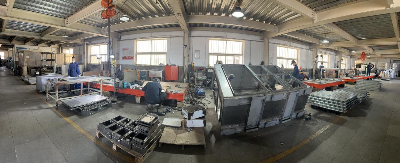
Electrostatic powder coating. Yinlu’s project records and product descriptions cite electrostatic powder coating on cold-rolled steel, and surface treatment is listed in its customization scope. Two points matter more than the colour. First, adhesion and corrosion resistance come from the pretreatment stage rather than the topcoat; a phosphate conversion coating is a standard pretreatment option before the powder stage, and if the project’s corrosion target depends on it, ask for the process sequence in writing. Second, powder adds thickness on mating surfaces — a device gasket land, a gland seat and an earth stud all change fit — so state which areas are masked and keep earthing points at bare metal.
Colour is a separate line. Where a project calls for a light-grey finish such as RAL 7035, the RAL reference belongs on the drawing together with the appearance criteria, because the same reference on different substrates and coating systems will not read identically.
Comparison table: matching the interface to the decision
| Interface element | Options to choose from | What it decides | What the drawing must state |
|---|---|---|---|
| Cable entry face | Bottom entry; pedestal or floor-plate entry | Water path, drip-loop space, gland access | Face, height above plinth, gland size and thread |
| Opening type | Pre-scored knockout; opening cut to the gland thread | Edge quality and the flat land for the gland washer | Opening size, tolerance, method, wall thickness at that point |
| Panel cutouts | Round device openings; rectangular meter and HMI windows; door or body mounted | Device fit, bezel sealing, wiring route | Two datums, dimensions, edge distance, corner radius, fixing centres |
| Door arrangement | Single leaf; double leaf with meeting stile | Access width and gasket continuity | Leaf widths, stile detail, hinge side, door swing |
| Door gasket | EPDM, continuous route | Sealing of the door joint | Material, route, joint at locks and hinges |
| Locking | Flat lock; handle lock with additional latch points | Gasket compression over door height | Lock type, latch points, keying |
| Surface treatment | Electrostatic powder coating; colour reference such as RAL 7035 | Corrosion resistance and fit at mating surfaces | Pretreatment, colour reference, masking list, earth points |
| Mounting | Surface wall; floor standing on plinth; pedestal; recessed | Which faces can be used for entry | Mounting type, clearances, rear access |
Application notes: PLC, outdoor and low-voltage cabinets
PLC electrical enclosures. A PLC cabinet concentrates many small signal cables behind one door, and the protection target may be IP54 in an indoor control room or IP66 in a washdown area. Because the second digit sets the water criterion, the entry detail changes with the target even when the cabinet looks the same. Keep power and signal entries on separate gland plates or separate areas, and keep signal entries away from the hinge side where the wiring harness moves.
Outdoor and weather-resistant cabinets. The stainless steel double-door outdoor cabinet and the free-standing outdoor control cabinet families both depend on bottom entry, a plinth or floor plate, and a door joint that sheds water. One leak path at the meeting stile or at a lock penetration is enough to fail the assembly, which is why the gasket route and the lock positions should be drawn together.
Low-voltage panel enclosures. Distribution and switchgear cabinets carry larger cables and heavier glands, so the entry schedule has to include cable support and bending space, not just hole size. In North America, ANSI/NEMA 250-2020 sets the scope at equipment rated not more than 1,000 V, which is where most of these cabinets sit.
Wall-mounted instrument and control boxes. Small boxes are the most common place for an undocumented field cut, because the installer often adds a cable entry on site. Specifying one or two spare bottom entries at order stage removes the temptation.
Custom and heavy-industrial builds. Cutouts and mounting are explicitly inside Yinlu’s customization scope, and the project record shows the same logic in practice: enclosures for a gas chromatograph were built with a modular partition that reserved channels for gas paths, circuits, heat dissipation and maintenance, and heavy-industrial cabinets for port and coke-oven machinery were customized by size, cutout, protection class and installation method, with protection classes quoted from IP55 to IP67 across documented builds. In those projects the cutout and entry drawing is the interface document between the equipment maker and the enclosure maker.
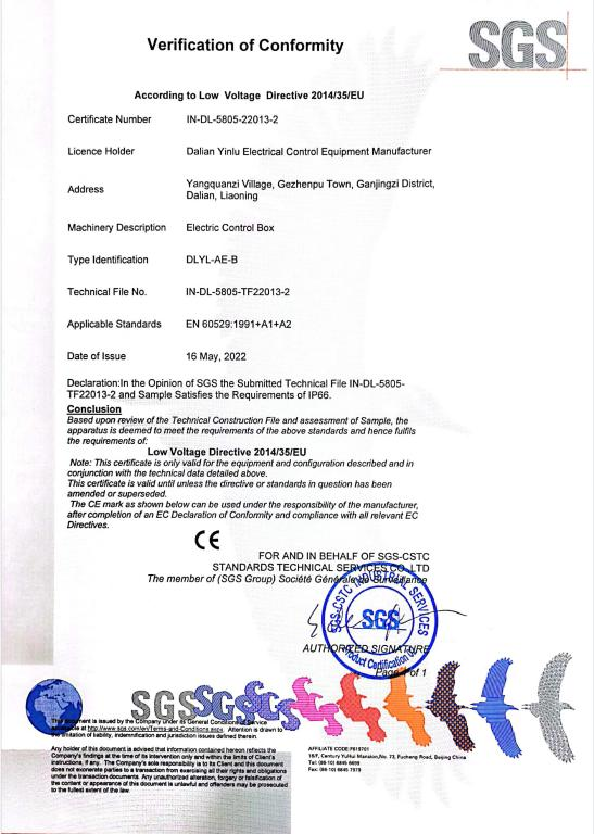
Compliance evidence. SGS-CSTC issued CE Verifications of Conformity to EN 60529:1991+A1+A2 for the DLYL-ES-C electric control cabinet (certificate IN-DL-5805-22013-1) and the DLYL-AE-B electric control box (IN-DL-5805-22013-2), both dated 16 May 2022 and referencing the EU Low Voltage Directive. Those records cover the named models as tested; they do not automatically extend to a modified configuration with new cutouts, which is why the drawing set matters as much as the certificate.
Pre-production checklist for cable entry and cutouts
- IP rating and reference standard stated, with the NEMA type added separately where required.
- Mounting condition fixed — surface wall, floor standing on plinth or pedestal — and recessed installations noted so rear entry is excluded.
- Cable entry schedule complete: cable outside diameter, gland type, thread, entry face, height and spare entries.
- Wall thickness stated at each entry, with reinforcing pads where the gland is large relative to the sheet.
- Cutouts dimensioned from two datums, with edge distances, corner radii, tolerance band and fixing centres.
- Door architecture confirmed: single or double leaf, meeting stile detail, gasket material and route.
- Lock type and latch points agreed, with door swing checked against the site layout.
- Coating system, colour reference and masking list agreed, including earth points.
- Sealing check included in the inspection plan alongside the documented visual, wiring, function, safety and packaging checks.
- Responsibility for field modifications written into the order rather than left to the installation crew.
FAQ
Does cutting a gland hole or a meter opening void the enclosure’s IP rating?
The rating as certified describes a specific tested configuration. Once an opening is added, protection at that point depends on the component fitted and on how the opening was made, so the installed assembly is a new configuration that should be documented and, where the project requires it, re-verified. The CE verification records held for the DLYL-ES-C cabinet and the DLYL-AE-B box apply to those named models as tested.
Can cutouts for instruments, buttons and meters be produced as part of the enclosure build?
Yes. Cutouts and mounting are listed in Yinlu’s customization scope alongside material, colour, logo, size, IP rating and surface treatment, under an OEM and ODM production model. The practical requirement is a drawing with two datums, edge distances, tolerances and fixing centres, because only what the drawing defines can be inspected.
What are the order terms, and how small can the first order be?
The recorded capability data lists an MOQ of 1 to 5 units against a monthly capacity of 2,000 units. The purchasing terms list delivery on FOB, CIF, EXW, DAP, CFR or DDP, payment by TT, PayPal, LC or Visa, and a power-on test as the acceptance criterion. Because entry and cutout work is configuration-specific, those terms are best confirmed against the final drawing set rather than at enquiry stage.
Can we run a small first batch to test cable entry fit and door sealing before committing to volume?
The low minimum order range makes a small validation batch practical. Build it against the production drawing — same gland types, same cutouts, same gasket — and check what is difficult to change later: gland thread engagement, the flat land around each cutout, gasket compression along the closing edge, and the meeting stile on a double door. Sealing is one of the documented quality control checks, so agree in advance what that check covers.
What lead time should be planned for a customized cabinet with cutouts and glands?
Lead time is recorded as negotiable and is therefore confirmed per order rather than published as a fixed figure. Three variables move it: the number and complexity of cutouts, whether the sheet thickness or reinforcing detail changes after approval, and the coating stage, which cannot start until the metalwork is final. Fixing the drawing set before the order is the most reliable way to protect the schedule.
If you are ready to specify, the Yinlu product brochure sets out the enclosure families and customization options, and the engineering team can review a cutout and entry drawing against your protection target before a quotation is issued.
Conclusion
Cable entry, panel cutouts and door sealing are not finishing details to be settled on site. They are the interfaces where an enclosure’s protection is either preserved or lost, and they can only be controlled through the drawing. Fix the protection target and the standard first, the mounting condition second, then build the entry schedule, the cutout drawing and the door architecture around them. Confirm thickness and coating where they change fit, and agree what the sealing check covers before production.
A cabinet that passes a sealing check in the factory and still leaks on site almost always has an undocumented opening, an unspecified gland or a gasket route that no one drew. Closing those three gaps costs less than any rework.
Have Questions or Need More Details?
Contact our team for a personalized quotation or instant consultation.
Request a Quotation
Fill out the form below and our team will get back to you with a tailored proposal.
WhatsApp Direct Chat
Prefer to chat in real-time? Message us on WhatsApp for instant assistance & quick answers.
- Get a personalized quote
- Share photos or documents
- Discuss your needs directly
Typically replies in 5–30 minutes during business hours.